로딩중...
검색중...
일치하는것 없음
Use your own device
이 가이드는 아직 번역되지 않았습니다.
Deki is modular and can run on almost any target with enough RAM. Your device does not have to be on the list: hardware support is a package like everything else, so you add what your device needs.
What you need
How you add a device depends on what it is.
| Your device | How to add it |
|---|---|
| An Espressif chip | The rest of this page |
| Anything else, such as a Linux handheld | A package with its own build backend, display and input, as deki-miyoo-boards has. Start from Platforms |
For an Espressif device you need:
- A chip ESP-IDF supports. The list offers them all. An ESP32-S3 with PSRAM is the safe choice: it is what every Espressif device on the list uses.
- A screen and touch controller Deki knows. See the table below.
- The device's pinout, from its schematic or its maker's example code.
| Part | Runs on a real device | Written and tested, not yet tried on a device |
|---|---|---|
| Screen | ST7789, RM67162 | ST7789P3, ILI9341, ST7796, ILI9488, ST7735, ST7735S, GC9A01, SSD1351, CO5300 |
| Touch | GT911, CST816S, CST816T | FT5x06, FT6x06, XPT2046 |
Copy the closest device
Starting from a device like yours saves most of the work. Install the package that has it, then copy it under a new name:
DekiEditor --tool create_platform --args '{"id":"my_device","from":"lilygo_t_deck","display_name":"My Device"}' <project>
The copy is yours, in your project's platforms/my_device/ folder.
To start with nothing instead, press + beside the platform list in the Build panel and pick ESP-IDF.
Open the platform with the pencil in the Build panel and set what is different: the chip, the resolution, the screen's diagonal, and the flash and PSRAM under Memory.
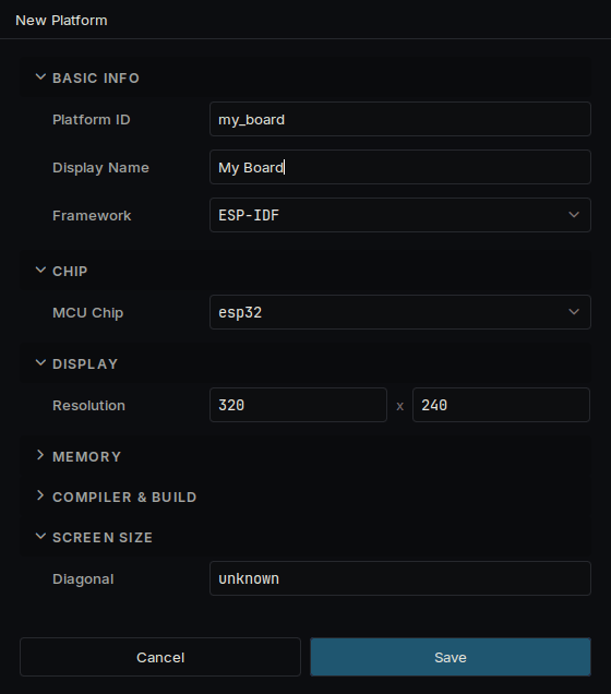
The settings of a platform
Say how it is wired
Open Build → Platform Manager..., choose your device and press Open Boot Scene. This scene runs when the device starts, and it never reaches the screen: each object under Setup is one step that brings a piece of hardware up.
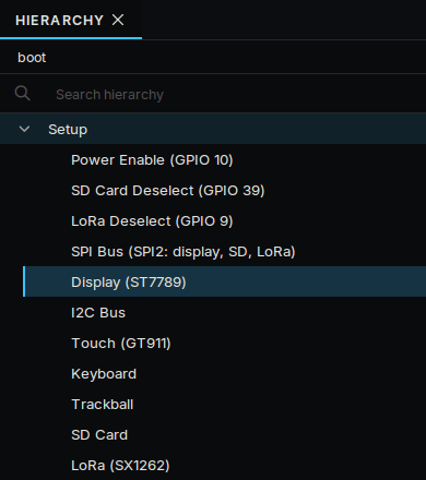
The steps of a boot scene, one object each
The steps run in the order of Setup Components, on the Setup object. The screen's bus has to come before the screen. For a part your device does not have, remove its line there and delete its object.
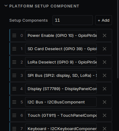
The order the steps run in
Select each step and set its pins in the Inspector.
| Step | What to set |
|---|---|
| Power pin | The pin that powers the screen, if your device has one |
| SPI bus | The bus and its clock and data pins |
| Display | Controller, Panel Width and Height, Rotation, and the pins |
| I2C bus | SDA and SCL |
| Touch | Controller and interrupt pin |
Panel Width and Height are the panel's own, before rotation: a 320 x 240 screen shown sideways is 240 wide and 320 high, with Rotation on Landscape.
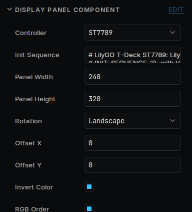
The display step in the Inspector
Build it
Choose your device in the Build panel and press Build & Flash. View → Serial Monitor shows the boot log, which says what started and what did not.
If the screen looks wrong
| What you see | What to change |
|---|---|
| Nothing at all | The power pin and the backlight pin. Some backlights are on when their pin is low |
| Noise, or a white screen | The Controller and the pins. Try a lower SPI clock |
| Colours like a negative | Invert Color |
| Red and blue swapped | RGB Order |
| Dark colours pink, white green | Swap Bytes |
| Picture shifted, with a strip of noise | Offset X and Offset Y |
| Sideways or upside down | Rotation |
| Washed out, or a ghost of the last image | Init Sequence, from the panel maker's own start-up code |
Make it fast
Most of it is chosen for you. These describe the wiring, which the device cannot find out by itself.
| Setting | Set it to |
|---|---|
| SPI clock (spiWriteHz) | The fastest the panel takes. Most ST7789 modules take 80 MHz; on a parallel bus, 20 MHz is safe |
| TE pin (tePin) | The GPIO the panel's TE output is wired to, if it is. The best way to stop tearing |
| readsOnMosi | On when the panel answers on its data line instead of MISO. Only matters without a TE pin |
Share it
Once it runs, you can put the device in a package so others can pick it from the list: Platforms says how.